


We have already learned in earlier post about how design IR Remote Control for Home Appliances. But, have you ever tried to design wireless communication circuit without any microcontroller? This article explains you how to control the home appliances wirelessly using RF technology.
Here we have used RF434 MHz modules to make wireless remote. Using this remote, we can control the appliances within the range of 100 meters. This project has two sections, one is transmitter section and the other is receiver section. At transmitter section, we use HT12E encoder and at receiver section, we use HT12D decoder.
RF Remote Control Circuit Principle:
When we press any key in the remote, the transmitter section generates the corresponding RF signal and this signal is received by the receiver section, hence it switches the corresponding appliance.
A four channel encoder/decoder pair is used in this system. The input signals at the transmitter section are taken from the four switches and the output signals at the receiver are indicated by the four LED’s corresponding to each switch.
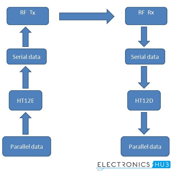
RF Communication
Here, the encoder HT12E is used to convert parallel data to serial. This data is transmitted serially to receiver point through RF.
RF receiver receives the data serially and then gives to the HT12D decoder to convert it to the parallel. Four LEDs indicate the received data.
Circuit Diagram of RF Remote Control for Home Appliances without using Microcontroller:
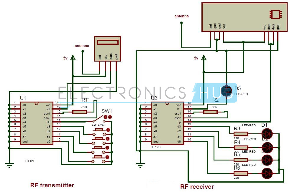
Circuit Diagram of Remote Control Circuit Through RF Without Microcontroller
Circuit Components:
- HT12E encoder IC
- HT12D decoder IC
- RF 434 MHz transmitter and receiver
- Resistors – 33k,750k
- 220 ohm Resistors – 4
- Push buttons – 4
- SPST switch – 1
- LEDs – 5
RF Remote Control for Home Appliances without Microcontroller Circuit Design:
HT12E Encoder: This encoder IC is integrated 2^12 series of encoders. This IC is mainly used to interface RF and IR circuits. This IC converts 12 bit parallel to serial. These 12 bits are divided into 4 data bits and 8 address bits.
This IC has transmitter enable pin. When trigger signal is received on this pin, the address and data bits are transmitted together. HT12E starts a 4 word transmission cycle upon receipt of enable. The transmission cycle is repeated till transmitter enable is kept low.
HT12D Decoder: Thisdecoder IC converts serial input data to parallel. This IC indicates valid transmission by a high at VT (Valid Transmission) pin.
HT12D is capable to decode 12bit data (8 address bits and 4 data bits). The output data remains unchanged till the new data is received.
It is mainly used in RF and IR circuits. These decoders are mainly used for remote control applications like burglar alarm, car door alarm, security system etc.
The chosen pair of encoder and decoder for communication should have same number of address and data bits.
RF Modules (434MHz):
This module operates at radio frequency. The Radio frequency range is 30 KHz to 300 GHz. In this system, RF modules use ASK (Amplitude Shift Keying) modulation.
Transmission through RF is better than IR because, the RF signal can travel for longer distances as compare to infrared. And IR mostly supports line-of-sight mode, RF signals can travel even there is an obstruction. RF transmission is more reliable and stronger as compare to IR.
The chosen pair of RF Transmitter and receiver should have same frequency. The transmission speed of these modules is 1Kbps to 10Kbps.
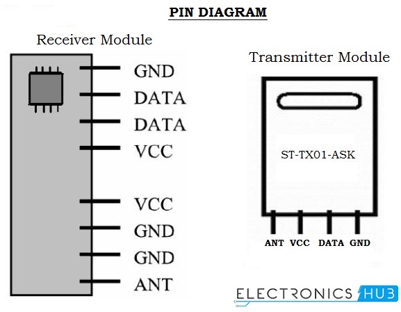
RF Modules Pin Diagram
How to Operate this RF Remote Control Circuit?
- Connect the circuit as shown in the diagram.
- Apply 5V supply to the transmitter and receiver sections. Now you can observe that all the LEDs at receiver will glow.
- Press the first button at transmitter section; you can observe that first LED will off at receiver section. In the same way when you press any button at transmitter section the corresponding LED at receiver will OFF.
- Now disconnect the power supply from transmitter and receiver sections.
RF Remote Based Home Automation System Project Output Video:
RF Remote Control Circuit Advantages:
- Works for longer distances as compared to IR.
- RF signals can travel even there is an obstruction between transmitter and receiver.
RF Remote Control Circuit Applications:
- Used for remote control applications like burglar alarm, car door alarm, calling bell, security systems, etc.
Limitations of the Circuit:
- The mode of communication is complex.
- As we are using ICs, they consume more power.


0 comments:
Post a Comment