Electronics Hub excellent educational blog for engineering students in providing great information on various electronics projects ideas, circuits, electronics tools, etc. from basic level to advanced level.

loading...

Project Ideas For EEE Students

Top and best electronics projects ideas for EEE students along with all sources like circuit diagram, code, abstract and output video

Electronics Engineering in Wireless Technology

Wireless communication is the transfer of information between two or more points that are not connected by an electrical conductor

Printed Circuit Board or PCB Technology

One of the key concepts in electronics is the printed circuit board or PCB

Electronics in Smartphones

A smartphone is a mobile phone with an advanced mobile operating system

Electronics Engineering Fun

Electronics Engineering, is an engineering discipline which utilizes non-linear and active electrical components.

Showing posts with label Communication. Show all posts

Wednesday, February 24, 2016

FM Remote Encoder/Decoder Circuit

We have already studied how to control the home appliances using RF communication in the post RF Remote Control Circuit for Home Appliances. Now let us see how to design FM remote encoder and decoder circuit using RF600E and RF600D ICs. This pair of encoder and decoder ICs establishes the communication with high level security. The operating voltage of these ICs is from 2V to 6.6V DC.
This system uses FM (Frequency Modulation) for transmission. If you press any push button then corresponding code is generated at transmission section. Here encoder is used to convert parallel data to serial. This serial data is given to the FM Tx module to transmit. FM Rx module receives this serial data and fed to the decoder to produce the corresponding output.

FM Remote Encoder and Decoder Circuit Diagram:

Transmitter Section:
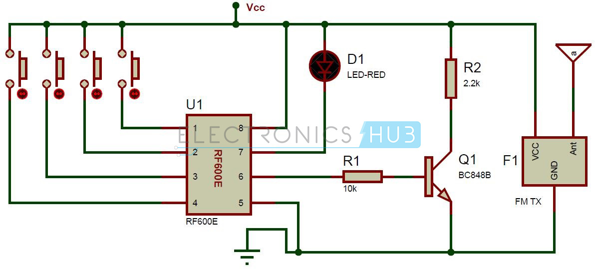
FM Remote Encoder and Decoder Circuit - Transmitter Section
FM Remote Encoder and Decoder Circuit – Transmitter Section
Circuit Components:
  • RF600E encoder
  • FM Transmitter module
  • 4 push buttons
  • Bc848 Transistor
  • Led
  •  Resistors – 2.2k, 10k

Receiver Section:
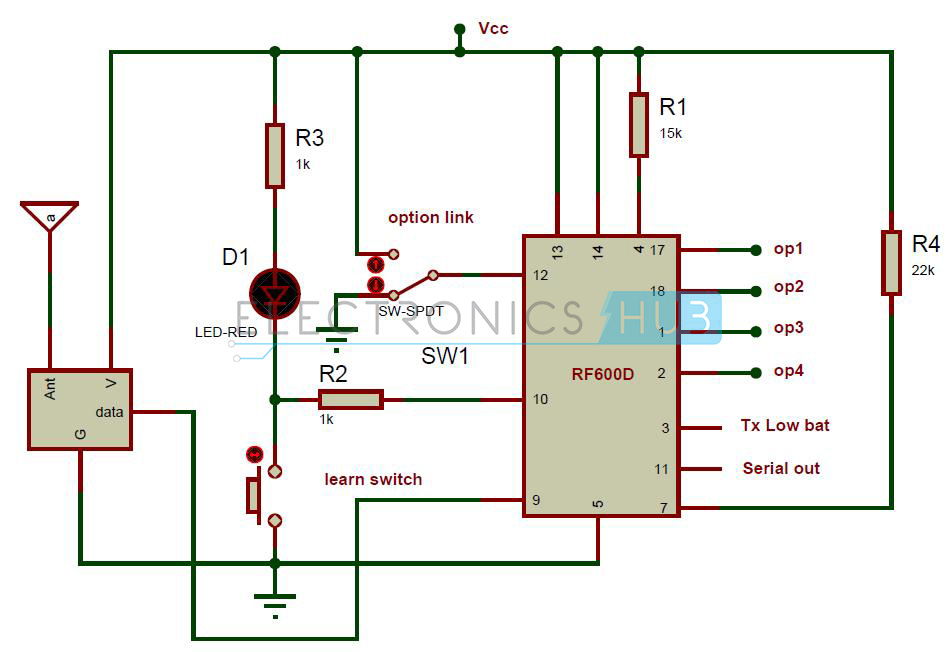
FM Remote Encoder and Decoder Circuit - Receiver Section
FM Remote Encoder and Decoder Circuit – Receiver Section
Circuit Components:
  • RF600D Decoder
  • FM Receiver module
  • Slide switch
  • Push button
  • Red LED
  • Resistors – 1k(2), 15k, 22k

FM Remote Encoder/Decoder Circuit Design:

The circuit mainly consists of two sections, one is Transmitter section used t transmit the remote data and other is Receiver section used to receive the data.
Transmitter Section:
This section consists of RF600E encoder, FM transmitter module, four switches and LED. Four push buttons are used to generate the parallel data. If you press any push button, then corresponding code is generated at the 6thpin of encoder. Here the LED which is connected to the 7th pin of encoder is used for indicating the signal transmission.
RF600E Encoder:
This pair of encoder and decoder ICs uses balanced Manchestar encoded data protocol for transmission. This encoder IC requires just fewer components to use it as a transmitter. The transmission is automatic there is no need of human intervention.
The data format includes a pre-amble, header, encrypted data followed by CRC bit. Here the packet size is 67 bits.
Low Battery Indication:
This encoder IC reads the battery status for each operation. If the voltage is below 3.8 volts then flag bit is transmitted to the decoder IC.
Pin Configuration:

PIN NO.

NAME

DESCRIPTION
1
S0
Input data pin0
2
S1
Input data pin1
3
S2
Input data pin2
4
S3
Input data pin3
5
Vss
Ground reference connection
6
OP
Data output pin
7
LED
Cathode connection for driving LED during the transmission
8
Vcc
Supply voltage pin
Receiver Section:
The receiver section consists of RF600D decoder and its associated components. Pins 17, 18, 1 and 2 are the digital output pins corresponding to the input switches. If you press any push button, then the corresponding pin at decoder becomes low. Here SPDT switch is used to select latching or memory digital function. The learn switch is used to enter the decoder IC into the “learn mode”.
RF600D Decoder:
In this RF chipset, protocol data is sent serially as a stream of ASCII characters with a baud rate of 9600 bits per second. While coming to the frame format 8 data bits with one stop bit.
Pin Configuration:
PIN NO.
NAME
INPUT/OUTPUT
DESCRIPTION
1
OP3
Out
Data output pin
2
OP4
Out
Data output pin
3
LB
Out
Pin goes low, when battery is low
4
Vcc
In
Supply voltage pin
5
Vss
In
Ground pin
6
ECS
Out
Connected to EEPROM CS pin
7
ECLK
Out
Connected to EEPROM CLK pin
8
EDAT
I/0
connected to EEPROM DATA PIN
9
IN
In
Data input
10
LRN
In
learn/erase switch and status LED drive
11
SD1
Out
serial data output
12
LKIN
In
Option Link Input for Momentary or Latched outputs
13
SLEEP
In
1 = Run, 0 = Sleep Mode
14
Vcc
In
Positive supply voltage pin
15
Unused
N/A
no connection
16
Unused
N/A
no connection
17
OP1
Out
Data output pin
18
OP2
Out
Data output pin

How to Operate FM Remote Encoder and Decoder Circuit?

  1. Give the connections as per the circuit diagram.
  2. Connect the LED’s at the decoder outputs.
  3. Apply 5V supply to the both transmitter and receiver sections.
  4. Initially all the LED’s will glow.
  5. Now press the first button at transmitter section, you can observe that first LED will off at decoder section. In the same way for each switch at transmitter the corresponding LED at receiver will off.
  6. Switch off the power supply for both transmitter and receiver sections.

FM Remote Encoder/Decoder Circuit Advantages:

  1. Stand alone operation
  2. LED indication of signal transmission
  3. Battery low indication
  4. Manchester modulation
  5. Sleep mode.

FM Remote Encoder/Decoder Circuit Applications:

  • Used in general purpose Remote control applications
  • Used in burglar alarm systems
  • used in automotive systems
  • Used in Electronic door locks
Circuit Limitation:
  • This circuit is theoretical and may require some practical changes.
Share:

RF Remote Control Circuit for Home Appliances

We have already learned in earlier post about how design IR Remote Control for Home Appliances. But, have you ever tried to design wireless communication circuit without any microcontroller? This article explains you how to control the home appliances wirelessly using RF technology.
Here we have used RF434 MHz modules to make wireless remote. Using this remote, we can control the appliances within the range of 100 meters. This project has two sections, one is transmitter section and the other is receiver section. At transmitter section, we use HT12E encoder and at receiver section, we use HT12D decoder.

RF Remote Control Circuit Principle:

When we press any key in the remote, the transmitter section generates the corresponding RF signal and this signal is received by the receiver section, hence it switches the corresponding appliance.
A four channel encoder/decoder pair is used in this system. The input signals at the transmitter section are taken from the four switches and the output signals at the receiver are indicated by the four LED’s corresponding to each switch.
RF Parellel to Parellel
RF Communication
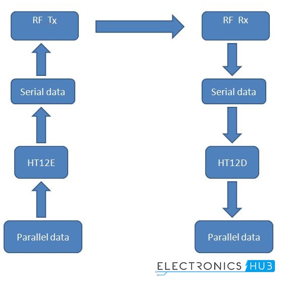
Here, the encoder HT12E is used to convert parallel data to serial. This data is transmitted serially to receiver point through RF.
RF receiver receives the data serially and then gives to the HT12D decoder to convert it to the parallel. Four LEDs indicate the received data.

Circuit Diagram of RF Remote Control for Home Appliances without using Microcontroller:

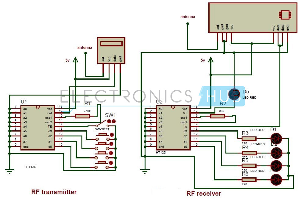
Circuit Diagram of Remote Control Circuit Through RF Without Microcontroller
Circuit Components:
  • HT12E encoder IC
  • HT12D decoder IC
  • RF 434 MHz transmitter and receiver
  • Resistors – 33k,750k
  • 220 ohm Resistors – 4
  • Push buttons – 4
  • SPST switch – 1
  • LEDs – 5 

RF Remote Control for Home Appliances without Microcontroller Circuit Design:

HT12E EncoderThis encoder IC is integrated 2^12 series of encoders. This IC is mainly used to interface RF and IR circuits. This IC converts 12 bit parallel to serial. These 12 bits are divided into 4 data bits and 8 address bits.
This IC has transmitter enable pin. When trigger signal is received on this pin, the address and data bits are transmitted together. HT12E starts a 4 word transmission cycle upon receipt of enable. The transmission cycle is repeated till transmitter enable is kept low.
HT12D DecoderThisdecoder IC converts serial input data to parallel. This IC indicates valid transmission by a high at VT (Valid Transmission) pin.
HT12D is capable to decode 12bit data (8 address bits and 4 data bits). The output data remains unchanged till the new data is received.
It is mainly used in RF and IR circuits. These decoders are mainly used for remote control applications like burglar alarm, car door alarm, security system etc.
The chosen pair of encoder and decoder for communication should have same number of address and data bits.
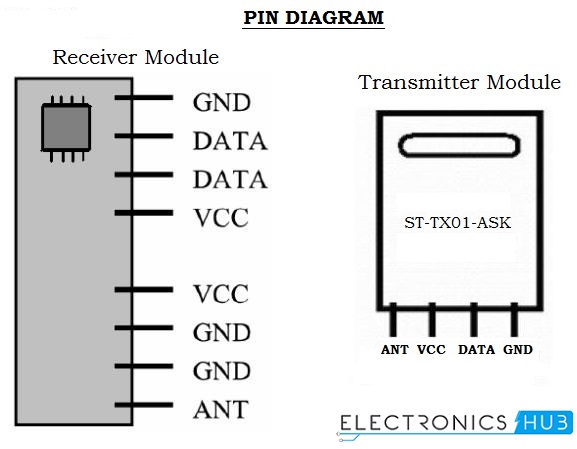
RF Modules (434MHz):
This module operates at radio frequency. The Radio frequency range is 30 KHz to 300 GHz. In this system, RF modules use ASK (Amplitude Shift Keying) modulation.
Transmission through RF is better than IR because, the RF signal can travel for longer distances as compare to infrared. And IR mostly supports line-of-sight mode, RF signals can travel even there is an obstruction. RF transmission is more reliable and stronger as compare to IR.
The chosen pair of RF Transmitter and receiver should have same frequency. The transmission speed of these modules is 1Kbps to 10Kbps.
RF Modules Pin Diagram

How to Operate this RF Remote Control Circuit?

  1. Connect the circuit as shown in the diagram.
  2. Apply 5V supply to the transmitter and receiver sections. Now you can observe that all the LEDs at receiver will glow.
  3. Press the first button at transmitter section; you can observe that first LED will off at receiver section. In the same way when you press any button at transmitter section the corresponding LED at receiver will OFF.
  4.  Now disconnect the power supply from transmitter and receiver sections.

RF Remote Based Home Automation System Project Output Video:

RF Remote Control Circuit Advantages:

  1. Works for longer distances as compared to IR.
  2. RF signals can travel even there is an obstruction between transmitter and receiver.

RF Remote Control Circuit Applications:

  • Used for remote control applications like burglar alarm, car door alarm, calling bell, security systems, etc.

Limitations of the Circuit:

  • The mode of communication is complex.
  • As we are using ICs, they consume more power.
Share: