Electronics Hub excellent educational blog for engineering students in providing great information on various electronics projects ideas, circuits, electronics tools, etc. from basic level to advanced level.
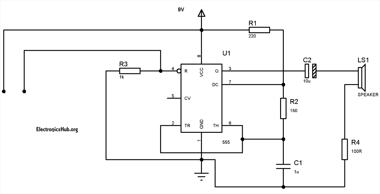
Circuit Diagram of Water Level Alarm using 555 Timer – ElectronicsHub.ga
The circuit uses a 555 timer in astable mode with R1=220 ohms, R2= 150 ohms and C1=1 uF. The frequency of the given astable circuit is around 1.18 KHz.
The two probes which are shown in the circuit should be kept at the high level for the water. The distance between the probes should be less than a few centimetres to ensure that the conduction between the probes will take place when water is touched to these probes.
When the water level rises to the height of the probes, then the 555 circuit will get enabled and the output of the 555 timer produces a square wave output with a frequency of about 1.18Khz. This output is given to the mini loudspeaker which then beeps at an audio frequency of 1.18KHz.
The logic Implemented in this circuit is, 555 timer is enabled when its reset pin is connected to logic high. But initially it is connected to ground. When the water level is maximum this pin is enabled and this drives the 555 timer into astable mode. Learn more about 555 timer.
Water Level Alarm Project Output Video:
Water Level Indicator Using Simple Transistors
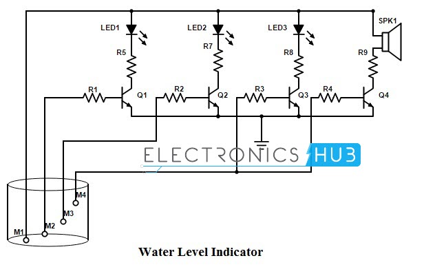
Water Level of the tank can be measured by using simple transistors also.
Components Required
BC547 transistors-Q1,Q2,Q3,Q4
Resistors R1,R2,R3,R4-8kohms
R5, R6 ,R7 – 1k ohm
Led – Red(LED3) , Green(LED1) , Yellow(LED2)
Buzzer-Buz1
Metal Contacts – M1,M2,M3,M4.
The circuit is designed to indicate three levels of water stored in the tank: low but not empty, half and full but not overflowing.
When there is no water in the tank, all the LEDs are off as an indication that the tank is completely empty. When water level increases and reaches M2, the contacts M1 and M2 get shorted as water acts as a conducting medium between M1 and M2.
This will turn on the transistor Q1 and the Green LED starts to glow. As the water level continues to rise and reaches half the tank, M3 will come into contact with water and receives a small voltage from M1.
As a result, Q2 is turned on and Yellow LED will glow. When the water in the tank rises to full tank, M4 is also shorted with M1 and both Q3 and Q4 will turn on.
The Red LED glows and also an alarm is made by the buzzer as an indication that the tank is full and the water pump or motor can be turned off.
Water Level Indicator Using ULN2003
One can implement this circuit using simple ULN2003 IC.IC ULN2003 consists of an array of seven Darlington transistor pairs.
Components Required
L1-L7-LEDs
R1-R7-330 ohm
M1-M7-Metal Contacts
ULN2003 IC
This IC can be used to indicate seven levels of water in tanks. When metal contact is reached ,each Led starts glowing.When the tank is full buzzer starts ringing along with this all LEDs are ON.


 Components Required
 Components Required