Electronics Hub excellent educational blog for engineering students in providing great information on various electronics projects ideas, circuits, electronics tools, etc. from basic level to advanced level.

loading...

Project Ideas For EEE Students

Top and best electronics projects ideas for EEE students along with all sources like circuit diagram, code, abstract and output video

Electronics Engineering in Wireless Technology

Wireless communication is the transfer of information between two or more points that are not connected by an electrical conductor

Printed Circuit Board or PCB Technology

One of the key concepts in electronics is the printed circuit board or PCB

Electronics in Smartphones

A smartphone is a mobile phone with an advanced mobile operating system

Electronics Engineering Fun

Electronics Engineering, is an engineering discipline which utilizes non-linear and active electrical components.

Showing posts with label 8051 Circuit Diagram. Show all posts

Wednesday, February 24, 2016

Speed Control of DC Motor Using Pulse Width Modulation

We use DC fans in many systems in our day to day life. For example, CPU fans, fume extinguishers and many more appliances which we make use of are operated by DC. Most of the times we will have a need to adjust the speed of the motors to our requirement. Although some systems have an automatic adjustment system for fan speed, not all systems possess this functionality. So, we will have to adjust the speed of our fan ourselves occasionally.
To adjust the speed of our fan manually, there are multiple ways to do that. We can adjust the speed by using a resistance in series with the motor. This is the simplest of all ways but it is not usually preferred because if we want to use any devices like microcontrollers or any other digital equipment for automating our DC fan speed, then this method will not work in general. A more efficient way to proceed is by using pulse width modulation technique to manage the speed of our DC motor.

Circuit Diagram of PWM Based DC Fan Controller:
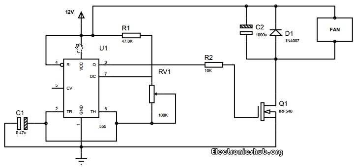
PWM DC Fan Controller Circuit
In this circuit, the DC motor is operated by a 555 integrated circuit. The IC 555 in this circuit is being operated in astable mode. In this mode, the circuit can be used as a pulse width modulator with a few small adjustments to the circuit. The frequency of operation of the circuit is provided by the passive parameters of resistances and capacitances attached to it. The resistance between pin-7 and pin-8, the resistance between pin-6 and pin-7 and the capacitance between pin-2 and the ground govern the frequency of operation and duty cycle of the ic 555 in astable mode. The duty cycle is governed by the resistor which is in between pin-6 and pin-7 of the IC 555 timer. So, by taking advantage of the circuits working, we can change the 555 astable multivibrator into a pulse width modulator by using a variable resistor instead of a constant resistor in between pin-6 and pin-7.
One of the best things about this circuit is that we can make it work as an astable multivibrator with little hardware and by little cost which can save both the cost involved in making it as well as the space on the printed circuit board is saved. if we want a sophisticated pulse width modulator which works more accurately and which can have more adjusting capabilities, then it is better to use a microcontroller based pulse width modulator than the one which we are using now. However, the circuit or the application for which we are using a pulse width modulator is not so sensitive and hence does not demand so much of accuracy. In such a case, the circuit which we are using with a bare IC 555 is better as it saves our monetary as well as space resources in building the circuit.
The duty cycle of the circuit can be changed by changing the resistance between pin-7 and pin-6. If we increase the duty cycle, the speed of the motor increases and if we decrease the duty cycle, the speed of the motor decreases.
Share:

Tuesday, February 23, 2016

Interfacing GPS with 8051 Microcontroller

A GPS module is a device that uses Global Positioning System to determine the location of a vehicle or person. GPS receivers are used to provide reliable navigation, positioning and timing services to the users at anytime and anywhere on the earth.  This Global positioning system uses 24 to 32 satellites to provide the data to the receivers. GPS has become very important for worldwide navigation and it is useful for land surveying, way marking, map-making, tracking and surveillance commerce and scientific uses. But, before going to know about this circuit, get an idea about how to interface LCD with 8051 Microcontroller.

Circuit Principle:

GPS module calculates the position by reading the signals that are transmitted by the satellites. Each satellite transmits the messages continuously which contains time was sent. GPS receiver measures the distance to each satellite based on the arrival time of each message. This information is used to calculate the position of the GPS receiver. The received raw data is converted for the user as LATITUDE, LONGITUDE, ALTITUDE, SPEED and TIME.

Circuit Diagram:

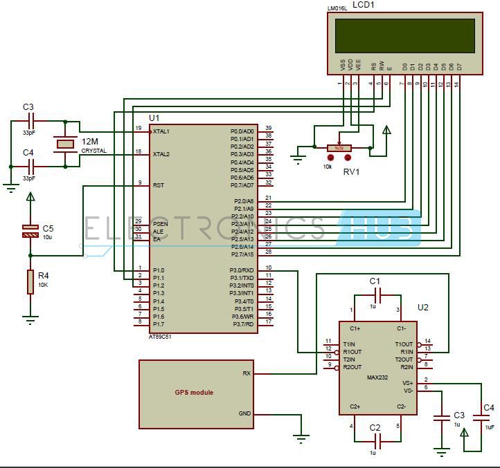
Interfacing GPS to 8051 Microcontroller Circuit Diagram
Circuit Diagram of Interfacing GPS to 8051 Microcontroller

Circuit Components:

  • at89c51 controller
  • Programming board
  • programming cable
  • 12V DC battery or adaptor
  • max232 IC
  • 16*2 LCD
  • GPS module
  • Pot 10k
  • 12 MHz crystal
  • Electrolytic capacitors – 1uF (4), 10u
  • Ceramic capacitors – 33pF (2)
  • Resistor – 10k

Circuit Design:

In the above circuit, LCD (Liquid crystal display) data pins are connected to PORT2 of the controller and control pins RS, RW and EN are connected to the P1.0, P1.1 and P1.2 respectively. The latitude and longitude values of the location are displayed on LCD. Here pot RV1 is used to adjust the contrast of LCD. The receiver pin of GPS module is connected to the 13th pin of max232 IC and GND pin is connected to ground. Controller RXD pin is connected to the 12th pin of max232. Here max232 IC is used for level conversion.
The GPS receiver continuously transmits the data as per the NMEA standards using RS232 protocol. In this NMEA format, the LATITUDE and LONGITUDE values of location are available in GPRMC sentence. In this project LATITUDE and LONGITUDE values are extracted from NMEA format and displayed on LCD.
We have to receive the data to the controller form GPS module serially using UART protocol and now extract the latitude and longitude values from the received messages and display them on LCD.
Extraction of Latitude and Longitude values from NMEA Format:
The first received 6 characters from GPS module are compared with string $GPRMC, if matched then will go for further process otherwise repeat the same process again. If string is matched then wait till you will get two 2commas, next character indicates weather the GPS is activated or not. If this character is A then GPS is activated otherwise GPS is not activated. Now again wait till you get comma (,). The next 9 characters indicate the LATITUDE. Wait till you get 2 more commas (,) the next 10 characters indicates the LONGITUDE.
If you want to check the latitude and longitude values of the location without any coding, then use Trimble studio software. This software directly provides latitude, longitude, altitude, speed, time and date when you interface GPS module. Even it provides your location in Google maps.
The below function is used to extract the LATITUDE and LONGITUDE values from the NMEA format.
void gps ()
{
unsigned int LAT[9], LON[10];
unsigned char Temp, i;
if (rx_data() == ‘$’)
{
if( rx_data() == ‘G’)
{
if (rx_data() == ‘P’)
{
if (rx_data() == ‘R’)
{
if (rx_data() == ‘M’)
{
if (rx_data() == ‘C’)
{
while (rx_data() != ‘,’);
/*checking for “A” condition*/
Temp = rx_data();
if (Temp == ‘A’||Temp == ‘V’)
{
while (rx_data() != ‘,’);
/*latitude values*/
LCDCmd (0x80);
for (i=0; i<9; i++)
{
LAT[i] = rx_data();
LCDData (LAT[i]);
}
while (rx_data() != ‘,’);
/*longitude values*/
LCDCmd (0xc0);
for (i=0; i<10; i++)
{
LON[i] = rx_data();
LCDData (LON[i]);
}
}
}}}}}}
}

Circuit Simulation Video:

How to Operate?

  1. Initially burn the program to the 8051 microcontroller
  2. Now give the connections as per the circuit diagram
  3.  Give the supply to the GPS module using adaptor
  4. Interface GPS module to the computer and open hyper terminal to check the received messages.
  5. Check whether the GPS is activating or not.
  6. Now connect the GPS to the circuit, you can observe that LCD displays latitude and longitude values.
  7. Switch off both the circuit and GPS module supplies.

Project Output Video:

Circuit Applications:

  • This system is used in marine navigation, car navigation and fleet management
  • Used in tracking devices and mapping devices
  • Used in personal positioning
  • This project is used in embedded system applications to find out the location.

Download Project Code

Note:
If you are interested to get code, kindly take some time and answer following questions in the comment section, so that we will send you the code.
  • Why you need this project code?
  • Are you trying to make the same project or different one?
  • Give us more details about your project.
Share:

Interfacing 16×2 LCD with 8051

In this session we will have brief discussion on how to interface 16×2 LCD module to AT89C51which is a 8051 family microcontroller. We use LCD display for the messages for more interactive way to operate the system or displaying error messages etc. interfacing LCD to microcontroller is very easy if you understanding the working of LCD, in this session I will not only give the information of LCD and also provide the code in C language which is working fine without any errors.

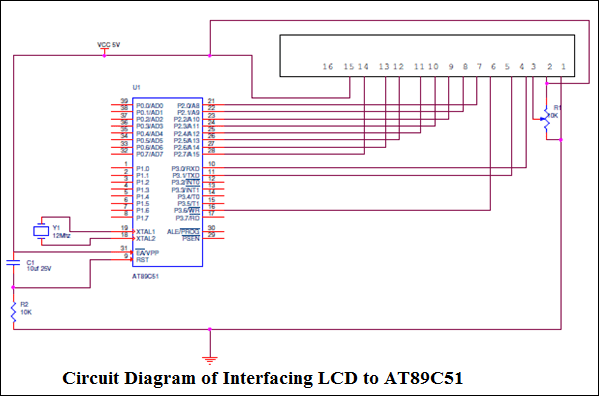
Interfacing 16×2 LCD with 8051 Circuit Diagram:

Interfacing LCD toAT89C51 Circuit Diagram

Interfacing LCD to AT89C51:

LCD: 16×2 Liquid Crystal Display which will display the 32 characters at a time in two rows (16 characters in one row). Each character in the display of size 5×7 pixel matrix, Although this matrix differs for different 16×2 LCD modules if you take JHD162A this matrix goes to 5×8. This matrix will not be same for all the 16×2 LCD modules. There are 16 pins in the LCD module, the pin configuration us given below
So by reading the above table you can get a brief idea how to display a character. For displaying a character you should enable the enable pin (pin 6) by giving a pulse of 450ns, after enabling the pin6 you should select the register select pin (pin4) in write mode. To select the register select pin in write mode you have to make this pin high (RS=1), after selecting the register select you have to configure the R/W to write mode that is R/W should be low (R/W=0).
Follow these simple steps for displaying a character or data
  • E=1; enable pin should be high
  • RS=1; Register select should be high
  • R/W=0; Read/Write pin should be low.
To send a command to the LCD just follows these steps:
  • E=1; enable pin should be high
  • RS=0; Register select should be low
  • R/W=1; Read/Write pin should be high.
Commands: There are some preset commands which will do a specific task in the LCD. These commands are very important for displaying data in LCD. The list of commands given below:
To get the detailed information, Click Here and Download the Datasheet

Circuit Explanation:

The crystal oscillator is connected to XTAL1 and XTAL2 which will provide the system clock to the microcontroller the data pins and remaining pins are connected to the microcontroller as shown in the circuit.  The potentiometer is used to adjust the contrast of the LCD. You can connect data pins to any port. If you are connecting to port0 then you have to use pull up registers. The enable, R/W and RS pins are should be connected to the 10, 11 and 16 (P3.3, P3.4 and P3.5).

Programming LCD to 8051:

Coming to the programming you should follow these steps:
  • STEP1: Initialization of LCD.
  • STEP2: Sending command to LCD.
  • STEP3: Writing the data to LCD.
Initializing LCD: To initialize LCD to the 8051 the following instruction and commands are to be embed in to the functions
  • 0x38 is used for 8-bit data initialization.
  • 0xFH for making LCD on and initializing the cursor.
  • 0X6H for incrementing the cursor which will help to display another character in the LCD
  • 0x1H for clearing the LCD.
Sending Data to the LCD:
  • E=1; enable pin should be high
  • RS=1; Register select should be high for writing the data
  • Placing the data on the data registers
  • R/W=0; Read/Write pin should be low for writing the data.
The program given below will use above functions and display the complete string which is given by the programmer to display the data. You have provided two demo codes working properly and easy to understand.
#include <REGX51.H>
#include <string.h>
#include <stdio.h>
sfr  LCD=0xa0;
sbit EN=P3^6;
sbit RS=P3^7;
voidnop(void);
void delay_1s(unsigned char t);
voidinitial_lcd(void);
void delay(void);
voidstring_to_lcd(unsigned char *s);
voidwrite_lcd(unsigned char dat,unsignedint com);
void delay_50ms(unsigned char x);
void main()
{
P0=0xff;
P1=0xff;
P3=0xff;
delay_50ms(4);
initial_lcd();
write_lcd(0x80,0);
string_to_lcd(”   WELCOME TO   “);
write_lcd(0xc0,0);
string_to_lcd(“INNOVATE ENG SOL”);
}
voidnop(void)
{
unsigned char n;
for(n=0;n<20;n++);
}
//………………delay routine……………..//
void delay_1s(unsigned char t)
{
unsigned char i,j;
for(i=0;i<t;i++)
{
for(j=0;j<20;j++)
{
TMOD=0x01;
TH0=0x3c;              //for 12MHz   (12/12MHZ)=1u>per cycle operation
TL0=0xb0;            //50ms delay get (50m/1u)=50000;
TR0=1;                 //Load value is =65536-50000=15536(=3cb0H)
while(TF0!=1);  //wait for overflow flag
TF0=0;
}
}
}
voidinitial_lcd(void)
{
write_lcd(0x38,0);
write_lcd(0x0c,0);
write_lcd(0x01,0);
}
voidwrite_lcd(unsigned char dat,unsignedint com)
{
RS=com;
LCD=dat;nop();
EN=1;nop();
EN=0;
nop();
}
voidstring_to_lcd(unsigned char *s)
{
unsigned char i,l;
l=strlen(s);
for(i=0;i<l;i++)
{
write_lcd(*s,1);delay_50ms(1);
s++;
}
}
void delay_50ms(unsigned char x)
{
unsigned char i;
for(i=0;i<x;i++)
{
TMOD=0x01;
TH0=0x3c;
TL0=0xb0;
TR0=1;
while(!TF0);
TF0=0;
TR0=0;
}
}
******************************** SECOND DEMO CODE*****************************
#include<reg51.h>
#define cmdport P3
#define dataport P2
#define q 100
sbitrs = cmdport^0;        //register select pin
sbitrw = cmdport^1;        //read write pin
sbit e = cmdport^6;        //enable pin
void delay(unsigned intmsec)    //Function to provide time delay in msec.
{
inti,j ;
for(i=0;i<msec;i++)
for(j=0;j<1275;j++);
}
voidlcdcmd(unsigned char item)    //Function to send command to LCD
{
dataport = item;
rs= 0;
rw=0;
e=1;
delay(1);
e=0;
}
voidlcddata(unsigned char item)    //Function to send data to LCD
{
dataport = item;
rs= 1;
rw=0;
e=1;
delay(1);
e=0;
}
void main()
{
lcdcmd(0x38);    //for using 8-bit 2 row mode of LCD
delay(100);
lcdcmd(0x0E);    //turn display ON for cursor blinking
delay(100);
lcdcmd(0x01);    //clear screen
delay(100);
lcdcmd(0x06);    //display ON
delay(100);
lcdcmd(0x86);    //bring cursor to position 6 of line 1
delay(100);
lcddata(‘A’);


}
Share: